There are many kinds of electronic connectors, but the manufacturing process is basically the same. According to engineer Hou from Joes Electronics, the manufacturing of connectors can be generally divided into four stages: stamping, electroplating, injection molding and assembly.
1. Stamping
The manufacturing process of electronic connectors produced by electronic connector manufacturers usually starts from stamping pins. The electronic connector (PIN) is made of thin metal strip by large high-speed stamping machine. One end of the large coil metal belt is fed into the front end of the stamping machine, and the other end passes through the hydraulic working table of the stamping machine and is wound into the tape feed roller. The metal belt is pulled out and by the tape feed roller rolled up, then the finished products are stamped out.
2. Electroplating
The connector pins shall be sent to the electroplating section after stamping. At this stage, the electronic contact surface of the military spec connector will be coated with various metal coatings. Similar to the stamping stage, problems such as pin distortion, breakage, or deformation will also occur when the stamped pins are fed into the electroplating equipment. Through the technology described in this paper, this kind of quality defects can be easily detected. However, for most machine vision system suppliers, many quality defects in electroplating process are still forbidden zones for detection systems. Custom connector manufacturers hope that the inspection system can detect various inconsistent defects such as fine scratches and pinholes on the electroplated surfaces of connector pins. These defects can be easily identified on other products (such as aluminum can bottoms or other relatively flat surfaces). Due to the irregular and angular surface design of most electronic connectors, it is difficult for the visual inspection system to obtain the images needed to identify these minor defects. Since some types of pins need to be coated with multiple layers of metal, manufacturers also hope that the detection system will be able to distinguish the various metal coatings in order to verify whether they are in place and in correct proportions. This is a very difficult task for vision systems using black-and-white cameras, because the image gray levels of different metal coatings are virtually the same. Although the camera of color vision system can successfully distinguish these different metal coatings, the problem of lighting difficulty still exists due to the irregular angle and the reflection effect of the coating surface.
3. Injection molding
The injection molding box base of the electronic connector is made in the injection molding stage. It is the usual process is to inject the molten plastic into the metal mold, and then form the base through rapid cooling. The so-called "omission" occurs when the molten plastic can not fully fill the mold, and it is a typical defect that needs to be detected in the injection molding stage. Other defects include the filling or partially clogging of the sockets (these sockets must be kept clean and unobstructed so that they can be correctly plugged into the pins in the final assembly). The machine vision system for quality inspection after injection molding is relatively simple and easy because the omission of box bases and the blocking of sockets can easily be identified using backlight.
4. Assembly
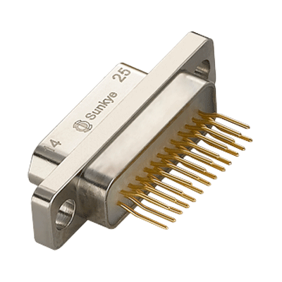
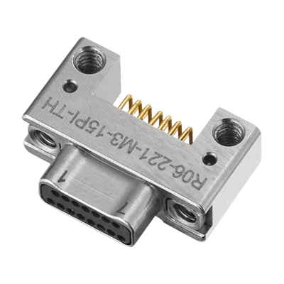
The final stage of electronic connector manufacturing is the assembly of finished products. There are two ways to connect the electroplated pin and the injection box base: single plug-in or combined plug-in. The single plug-in is to insert one pin at a time; the combined plug-in is to connect multiple pins with the box base at the same time. No matter which type of insertion is adopted, manufacturers require to inspect the omission and the correctness of positioning of all pins during the assembly stage; another kind of routine detection task is related to the spacing measurement of the connector matching surface. Just like the stamping stage, the military connector assembly also poses a challenge to the detection speed of the automatic detection system. Although most assembly lines detect one to two pieces per second, the visual system usually needs to complete several different detection items for each connector passing the camera, so the detection speed becomes an important system performance index again. After the assembly, the external dimensions of the connector on the order of magnitude is greater than the allowable dimensional tolerances of a single pin, which also poses another problem for visual detection systems. For example, some connector box bases are over a foot in size and have hundreds of pins, and detection precision of each pin position must be within one thousandths inch in size. Obviously, the detection of a one-foot-long connector cannot be completed in a single image, and the visual detection system can only detect the quality of a limited number of pins in a small field of vision at a time. There are two ways to complete the detection of the entire connector: Use multiple cameras (it will increase the system cost); or trigger the camera continuously when the connector passes in front of a lens, and the visual system stitches the single-frame images taken continuously together to judge the quality of the entire connector. The latter detection method is usually adopted by PPT visual detection system after the assembly of connectors.
Enable GingerCannot connect to GingerCheck your internet connection
or reload the browserDisable in this text fieldRephraseRephrase current sentenceEdit in Ginger×
 English
  日本語
日本語  한국어
한국어  français
  Deutsch
  Español
  italiano
  русский
  Türkçe
  Svenska
  Nederland