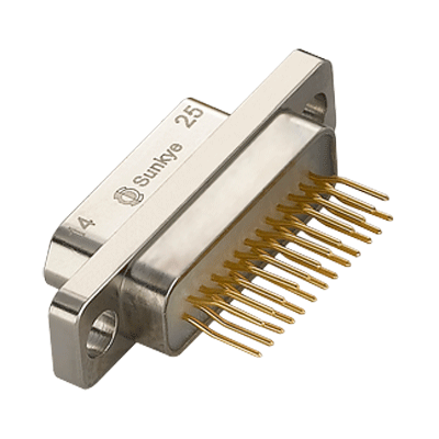

MIL-DTL-83513 Micro D Connectors

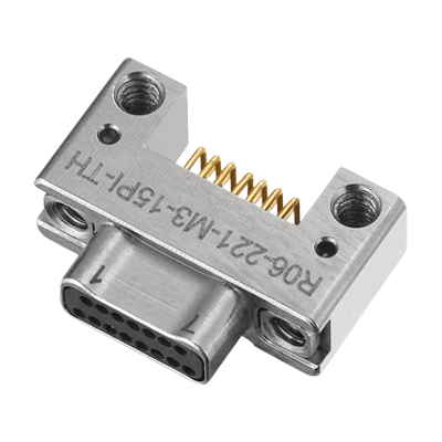
MIL-DTL-32139 Nano D Connectors
Discover more applications using Sunkye Connectors' solutions

Today, the clock frequency of electronic systems reaches hundreds of MHz, and the front edge and back porch of the pulse used are in the subnanosecond range. High quality video circuits adopts subnanosecond pixel rates. These high processing speeds indicate the continuous challenges in engineering. So how to prevent and solve the problem of connector electromagnetic interference is worth our attention.
The oscillations on the circuit become faster (rise/fall time), the voltage and current amplitude become larger, and the problems become more numerous. Therefore, it is more difficult to solve electromagnetic compatibility (EMC).
Before two nodes of the circuit, the pulse current that changes rapidly represents the so-called differential mode noise source. The electromagnetic field around the circuit can be coupled to other components and intrude into the connecting part. The noise of inductive or capacitive coupling is a kind of common mode interference. The RF interference current is identical to each other, and the system can be modeled as it consists of a noise source, a "victim circuit" or receiver and a loop (usually a baseplate). Several factors are used to describe the magnitude of the interference: the intensity of the noise source, the size of the surrounding area of the interference current, and the change rate.
Thus, although unwanted interference is likely to occur in the circuit, the noise is almost always a common mode. Once the cable is connected between the input/output (I/O) connector and the housing or the ground plane, a few milliamps of RF current is sufficient to exceed the permissible emission level when some RF voltage appears.
The coupling and spreading of noise
The common mode noise is caused by the unreasonable design. Some typical reasons are that the length of individual wire in different line pairs is different, or the distance to the power plane or housing is different. Another reason is the defect of components, such as the defect in magnetic induction coils, transformers, capacitors and active devices ( specific integrated circuit (ASIC) is required).
Magnetic components, especially the so-called iron-core choking coil type energy storage inductors, always produce electromagnetic fields when they are used in power converters. The air gap in the magnetic circuit is equivalent to a large resistance in a series circuit, where more electric energy is consumed.
Therefore, the iron-core choking coil is wound on the ferrite rod, and a strong electromagnetic field generates around the rod. The strongest electromagnetic field is near the electrode. There must be a gap on the transformer when using the switching power supply with the retracing structure. There is a strong magnetic field in the gap. The most suitable element to maintain the magnetic field is the shelix tube, which makes the electromagnetic field distribute along the length of the die. This is one of the reasons why the helical structure is preferred for magnetic elements working at high frequency.
Improper decoupling circuits often become interference sources. If the circuit requires a large pulse current, and the need for small capacitance or very high internal resistance cannot be guaranteed when the circuit is partially decoupled, the voltage generated by the power supply circuit will drop. This is equivalent to the ripple wave, or to a rapid change in voltage between terminals. Due to the packaged stray capacitance, the interference can be coupled to other circuits, causing the common mode problem.
When the common mode current contaminates the I/O interface circuit, the problem must be solved before the circuit flows through the connector. Different methods are suggested to solve this problem in different applications. The I/O signals are single ended and share the same common circuit in video circuits, so small LC filters can be used to filter out the noise to solve this problem.
In low frequency series interface networks, it is enough for some stray capacitances to shunt the noise to the baseplate. In the interface of differential drive such as Ethernet, the noise is usually coupled to the I/O area through a transformer, and the coupling is provided at the central tap on one or both sides of the transformer. These central taps are connected to the baseplate via a high voltage capacitor, and the common mode noise is shunted to the baseplate so that the signal will not be distorted.
The common mode noise in I/O area
There is no universal solution to all types of I/O interfaces. The main goal of designers is to design the circuit well, but they often ignore some simple details. Some basic rules can minimize the noise before it reaches the connector:
1) Set the decoupling capacitor close to the load.
2) The loop size of the fast changing front edge and back porch pulse currents should be the smallest.
3) Keep high current devices (i.e. drivers and ASIC) away from I/O ports.
4) Measure the signal integrity to ensure the minimum overshoot and undershoot, especially for critical signals with high current (such as the clock and bus).
5) The RF interference can be absorbed by local filter, such as RF ferrite.
6) Provide low impedance lapping or the standard of the I/O area to the baseplate.
Even if engineers take many of the precautions listed above to reduce RF noise in the I/O area, there is no guarantee that these precautions will be successful enough to meet the emission requirements. Some of the noise is conducted interference, which flows on the internal circuit board according to the common mode current. This interference source is between the baseplate and the circuit.
Thus, the RF current must flow through the access with the lowest impedance (between the baseplate and the carrier signal line). If the connector does not present a sufficiently low impedance ( at the lap joint with the baseplate), the RF current will flow through stray capacitors. When this RF current flows through the cable, the emission is inevitable.
Sunkye Connection Technologies provides a wide product portfolio with a complete interconnect solutions offering. Sunkye connectors and cables assemblies are complementary with Sunkye backshells and conduits.


 Jan 07, 2020
The Performance Of Automobile Connector
 Jul 17, 2024
MEET SUNKYE AT ONS 2024
 Dec 14, 2019
Naming Of Connectors
 Jul 09, 2020
The Importance of Connectors in Medical Equipment
 Apr 13, 2020
Why is a Poor Connector Prone to Fire?
 Nov 03, 2019
Some Solutions For Poor Terminal Pressing
 Feb 25, 2020
How to Choose the Right Medical Connector
 Nov 10, 2020
The Manufacturing Process of Electronic Connectors
 Aug 02, 2021
Introduction to Vehicle Connectors
 Jan 23, 2026
Building the Backbone of Deep Sea Sensing
 Oct 06, 2020
Description of Pogo Pin Connectors
 Oct 02, 2023
MEET SUNKYE AT ADIPEC 2023 FAIR
 Nov 01, 2019
Five Common Features of USB Connector
 Sep 06, 2019
Polytetrafluoroethylene-PTFE
 Sep 02, 2019
Four Processes of Producing Connectors
 Feb 07, 2020
The Rapidly Growing Market For Medical Connectors
 May 31, 2019
TWIST PIN: THE LIGHTSPOT OF SUNKYE
 Feb 15, 2021
The Power Capacity of RF Coaxial Connectors
 Apr 04, 2020
The Material of the Connector
 Jan 03, 2024
Connector — A Big Player in Your Supply Chain
 Oct 20, 2020
The Failure Mechanism of Connectors
 Jan 18, 2021
Knowledge of FPC Connectors
 Dec 23, 2019
Technical Principles Of Connectors
 Dec 11, 2019
The Main Classification Of Crimp Connection
 Sep 12, 2019
Reliable Connectors Are the Secret of UAV Success
 Nov 17, 2022
Robotic Arm Works 7*24 in Manufacturing
 Jan 16, 2020
Brief Introduction Of Strip Connector
 Jan 13, 2020
Overall Performance Parameters Of Connector
 Dec 01, 2021
Connectors' Revolution of 1000km off The Earth
 Feb 10, 2020
The Function And Prospect Of Medical Connector
 Oct 10, 2019
Types and Advantages of D-sub Connectors
 Nov 04, 2019
How Military Connectors Work
 Aug 02, 2020
Electrical Performance of Connector
 Nov 10, 2020
Applications and Characteristics of BNC Connectors
 Jun 25, 2019
Sunkye Super Pin Datasheet
 Oct 25, 2024
Harnessing Wind Energy: Sustainable Power Solutions
 Jun 18, 2020
Application of Military Electrical Connectors (1)
 Nov 23, 2022
Hermetic Connectors for Implantable Medical Devices
 Jun 15, 2020
7 Tips for Connector Design (2)
 Jul 18, 2020
The Basic Structure of the Connector
 Sep 25, 2020
Related Knowledge of SMA RF Connector
 Mar 29, 2020
Demand for Heavy Truck Connectors Increases
 Oct 31, 2019
The Introduction Of SMT
 Nov 06, 2019
Connector Classification
 Jan 19, 2020
Brief Introduction Of Flat Cable Connector
 Jul 03, 2020
Manual Assembly of Connectors (1)
 Aug 07, 2019
A Revolution in Connector Technology
 Dec 18, 2025
How to Survive During the Low Earth Orbit (LEO)?
 Jul 30, 2019
Market Status of Micro Connectors
 Sep 13, 2020
Fusion of Connectors and Sensors
 Oct 30, 2019
D Sub Connector Introduction
 Dec 29, 2019
Material Of Automotive Connectors
 Nov 08, 2019
Miniaturization Development Technology Of Connector
 Nov 24, 2019
The Connector Applications Are Everywhere
 Jan 31, 2020
The Development Of D-sub Connectors
 Dec 01, 2020
How to Improve the Reliability of RF Connectors
 Sep 20, 2019
Strictness of Military/Aerospace Specifications
 Oct 06, 2019
How Military Spec Connectors Work
 Mar 08, 2020
Sunkye: Safety, Innovation, Reliability
 Jul 06, 2020
Manual Assembly of Connectors (2)
 Dec 22, 2020
The Transient Interruption Detection of Connectors
 Nov 12, 2019
Production Technology of Connector
 Oct 18, 2022
Hermetic Connectors for Implantable Medical Devices
 Dec 22, 2024
Specialty Gas Connectors for Niche Applications
 Aug 01, 2022
Connectors Make Sensors Work Well on Equipment
 Oct 13, 2020
Various Coaxial Connectors
 Sep 04, 2019
Market Profile of Micro PCB Connectors
 Oct 13, 2020
Selection Factors of RF Connectors
 May 27, 2021
The Importance of Connectors in Electrical Equipment
 Jan 25, 2020
Four Types Of Industrial Electrical Connectors
 Jul 12, 2020
Introduction to the Connector
 Sep 14, 2019
Miniaturization Trend of Mil Connectors
 Aug 19, 2024
Can a Connector Withstand Temperatures Up to 500°C?
 Feb 19, 2020
Reliability of Aerospace Electrical Connectors
 Jun 24, 2020
Application of Military Electrical Connectors (3)
 Sep 26, 2019
Market Status of Micro Miniature Connectors
 Nov 29, 2019
Importance Of Connectors
 Nov 17, 2020
Selection Factors for SMA Connectors
 Aug 15, 2023
Extreme Conditions Bring up Hermetic Connectors
 Dec 08, 2020
Some Knowledge about RJ45 Connector
 Nov 17, 2023
Future Development Trends of Circular Connectors
 Nov 09, 2019
Introduction To Connector Knowledge
 Sep 21, 2021
Connection Mode and Purchase of Aerospace Connector
 Nov 11, 2019
Brief Introduction Of Automobile Connector
 Jan 01, 2020
Development Trend Of Automobile Connector In China
 May 31, 2019
Features of Type C
 Feb 13, 2020
Connection Between Brain And Machine
 Oct 19, 2021
Subsea Connector needs a new revolution
 Sep 28, 2019
Development Trend of Miniature Connectors Technology
 Dec 08, 2019
Connection Methods Of The Connector
 Jan 25, 2021
The Analysis of Connector Electroplating Problems
 Sep 24, 2019
Notes for Welding D Type Connector
 May 13, 2020
Reliability of Aerospace Electrical Connectors (2)
 Jul 17, 2020
Sunkye Market Matrix
 Aug 03, 2019
Connector D Type
 Sep 28, 2021
Correct Use and Safety of Avionics Connectors
 Oct 13, 2023
Several Design Ideas for Electronic Connectors
 Jan 11, 2021
How to Select Connectors for Hardware Design
 Dec 26, 2019
How To Classify Industrial Connectors
 Nov 14, 2019
How To Choose The Right Connector
 Jul 15, 2020
Classification of Connectors
 Apr 01, 2020
Connectors for Special Applications
 Jun 12, 2020
7 Tips for Connector Design (1)
 Sep 08, 2019
What are Avionics Connectors?
 Aug 09, 2021
What Are High Density Connectors?
 Jul 21, 2020
What is a Military Specification Circular Connector?
 Jan 28, 2020
The Connector Industry Is Booming
 Oct 07, 2020
How to Distinguish FFC Connector and FPC Connector
 Nov 05, 2019
Wearable Connectors Tend to be Miniaturization
 Jun 27, 2020
Crimping and Welding of Military Connectors
 Apr 25, 2020
The Second Generation Circular Military Connector
 Feb 08, 2021
Four Attention Points in Using Power Connectors
 Sep 08, 2022
How Does Environment Temperature Affect Connectors?
 Jul 08, 2021
Structural Analysis of Aerospace Connector
 Sep 19, 2020
The Necessity of Waterproof Connectors
 Jan 22, 2020
Differences Between Connector And Terminal
 Jan 04, 2023
Four Connection Methods of Circular Connectors
 Sep 18, 2019
Definition of Mil Standard Connector
 Apr 07, 2020
Market Status of Miniature Connectors
 May 31, 2019
Sunkye at Expo Electronica 2014, Moscow
 Nov 10, 2019
The Future Trend Of Automobile Connector
 Dec 17, 2019
Interconnection Level Of Connector
 Jun 21, 2020
Application of Military Electrical Connectors (2)
 May 10, 2020
Reliability of Aerospace Electrical Connectors (1)
 May 04, 2020
Automotive Connectors
 Nov 01, 2021
Meet Sunkye at SEDEC 2020 Fair!
 Dec 05, 2019
Disassembly Tools For Automotive Connectors
 May 31, 2019
Everything You Need to Know: Type C
 Nov 03, 2020
The Guide for Selecting Electrical Connectors
 Mar 20, 2020
Connector Quality Test Type
 Oct 01, 2020
Structure and Material of Waterproof Connector
 Nov 02, 2021
MEET SUNKYE AT SAHA EXPO 2021 FAIR!
 May 31, 2019
Sunkye Super Pin Connector
 Jun 06, 2019
Alloy 52 UNS N14052 Material Report
 Nov 15, 2019
How To Make High-Quality Connector
 Jan 04, 2021
The Structure and Material of Connectors
 May 31, 2019
Sunkye Type C 10Gbps Test on April
 May 31, 2019
SUNKYE will Release Type C Project on October
 May 31, 2019
Sunkye Will Postpone the Release of USB 3.1 Type C
 Aug 09, 2019
Development of Micro Connector
 Apr 28, 2020
How to Detect Medical Connectors
 Apr 22, 2020
Production Process of Connector Contacts
 Dec 02, 2019
Basic Structural Member Of Connector
 Jun 01, 2021
Functions and Advantages of Electrical Connectors
GET IN TOUCH
MIL-DTL-32139 Nano D Connectors
 English
  日本語
日本語  한국어
한국어  français
  Deutsch
  Español
  italiano
  русский
  Türkçe
  Svenska
  Nederland

