BNC connectors are very similar to the B and C terminals. A type of threaded connector TNC has better performance than BNC in microwave band.
There are 50 and 75 Ohm versions of the BNC connector. Transmission errors are less likely to occur when 50 Ohm connectors are connected to other impedance cables. Different versions of custom connectors are compatible with each other, but the signal may be reflected if the cable impedance is different. Usually BNC connectors can be used in 4GHz or 2GHz occasions. The 75 Ohm connector is used for the video and DS3 connection to the central offices of telephone companies, while the 50 Ohm connector is used for data and RF transmission. The socket may be damaged if a 50 Ohm plug is improperly connected to a 75 Ohm socket. 75 Ohm connectors are used in VHF applications.
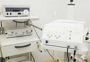
The BNC connector is used for the transmission of radio frequency signals, including the transmission of analog or digital video signals, antenna connections for ham radio equipment and the connection of avionics and other electronic test equipment. In consumer electronics, the BNC connector for video signal transmission has been replaced by RCA terminals, and RCA terminals can be used on devices with only BNC connectors through simple adapters.
BNC terminals have been widely used in 10Base2 Ethernet, and it is difficult to see network cards with BNC terminals because coaxial cables are replaced by twisted pairs. Some ARCNET networks use coaxial cables with BNC terminals.
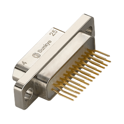
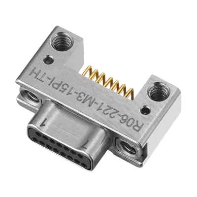
The BNC connector is suitable for low powered coaxial cables with the bayonet connection mechanism in the frequency range of 0-4GHz. This kind of connector can be quickly connected and separated, and it has reliable connection, good vibration resistance as well as convenient connection and separation, which is suitable for occasions that require frequent connections and separations. It is widely used to connect coaxial radio frequency cables in radio equipment and test instruments.
The characteristic impedance is very important, otherwise it will cause mismatching. When the impedance matches the military style electrical connectors, the maximum output power can be obtained and the equipment utilization efficiency is the highest. When the impedance does not match the connector, the effective output power will decrease. An impedance matching can be realized when the external impedance is equal to the internal impedance of the device.
The BNC connector must be connected to both ends of each cable segment. The BNC cable connector consists of a central pin, a jacket and a booth. It includes three parts: the BNC connector base, the jacket and the probe. The BNC connector was named according to the way it locks and its inventors Paul Neal of Bell Laboratory (who invented the N-terminal) and Carl Conseiman of Amphenol Corporation (who invented the C-terminal).
The NC connector is very similar to the B and C terminals. A type of connector TNC(Threaded Neill-Concelman) has better performance than BNC in microwave band.
The BNC connector is used for the transmission of radio frequency signals, including the transmission of analog or digital video signals, antenna connections for ham radio equipment and the connection of avionics and other electronic test equipment.
In consumer electronics, the BNC connector for video signal transmission has been replaced by the RCA terminals, and RCA terminals can be used on devices with only BNC connectors through simple adapters. BNC terminals have been widely used in 10Base2 Ethernet, and it is difficult to see network cards with BNC terminals because coaxial cables are replaced by twisted pairs. Some ARCNET networks use coaxial cables with BNC terminals.
Main characteristics of BNC:
1. The characteristic impedance
The characteristic impedance of 50Ω and 75Ω are used mostly in the BNC RF connector. Many series connectors have the specifications of 50Ω and 75Ω at the same time. In general, 50Ωconnectors are used in products with high frequency and high performance; 75Ω connectors are used in products with lower frequency, and the frequency is usually under 4 GHZ. Particularly, consumer electronics videos adopt 75Ω connectors more. Uses should select connectors that match the impedance of their own products. For example, a 75 Ω connector should be selected if the user is using a 75Ω RG 59 Cable.
2. The frequency
Each RF connector has a use frequency range, and users need to know the operating frequencies of their own products when selecting connectors. The connector frequency that is below the required operating frequency will affect the electrical performance of the whole machine, or choosing expensive high-precision and high-frequency connectors can be wasteful. It should be noted that the use frequency of connectors designed by different companies is quite different, and the use frequency of inferior products is far from meeting industry requirements. Therefore, users should confirm the electrical perf
ormance description of the product when selecting connectors.
3. VSWR
VSWR is one of the most important performance indicators of mil spec RF connectors and a measurement standard of the signal amount that returns from the connector. It is a vector unit including the amplitude and phase components. The VSWR of connectors of the same model is different at different frequencies. In general, the VSWR increases with the increase of the operating frequency. Users can enquire the manufacturer if they want to know the VWSR at a particular frequency of the connector.
 English
  日本語
日本語  한국어
한국어  français
  Deutsch
  Español
  italiano
  русский
  Türkçe
  Svenska
  Nederland